What if your "safe" pressure system is actually a liability because of a minor 4% margin of error? In New Zealand, if a valve lifts outside the strict tolerances mandated by WorkSafe, it's considered a failure and a potentially notifiable incident. Achieving precision in safety relief valve sizing NZ is about more than just matching pipe diameters. It requires a deep understanding of the PECPR Regulations 1999 and the specific lift tolerances for your operating pressure. You likely feel the weight of choosing between complex ASME and BS formulas while worrying about the catastrophic risks of an undersized system.
We believe that industrial safety shouldn't be a guessing game. This guide provides the technical clarity you need to master the sizing process and verify discharge capacity with total confidence. We'll walk you through the critical variables, including the mandatory 0.25% lead-free limit for potable water effective as of May 2, 2026, and the mandatory inspection cycles required by AS/NZS 3788. You'll gain a clear roadmap to a safe, compliant pressure system that meets every New Zealand engineering standard and protects your site from avoidable failures.
• Learn why relying on pipe line size is a critical engineering mistake and how to accurately calculate the required orifice area for your specific system.
• Identify the technical variables needed for precise safety relief valve sizing NZ, including how to determine mass flow rates for worst-case upset scenarios.
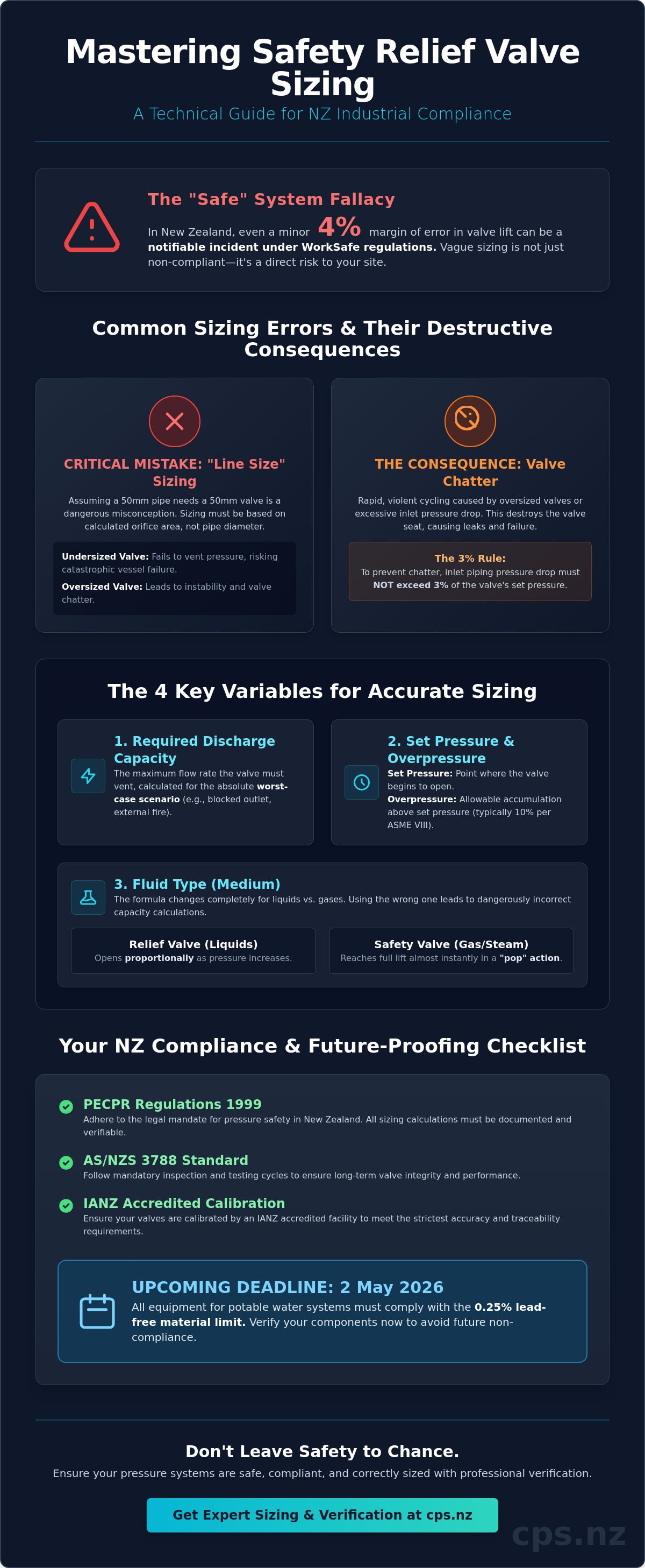
• Avoid the destructive effects of "valve chatter" by mastering the 3% rule for inlet piping pressure drop to ensure long-term valve seat stability.
• Discover how to align your sizing calculations with the latest 2026 New Zealand regulatory standards, including IANZ accredited calibration and lead-free material requirements.
In New Zealand's industrial sectors, the process of safety relief valve sizing NZ is a critical engineering task that determines the safety of every pressure-retaining vessel. Fundamentally, sizing is the calculation of the minimum orifice area required to discharge a specific mass or volumetric flow rate under a defined overpressure scenario. It isn't a simple matter of matching the valve to the existing pipework. While many operators assume that a 50mm pipe requires a 50mm valve, this "line size" approach is a dangerous misconception. An oversized valve can lead to rapid cycling or "chatter," which destroys the valve seat and prevents the system from venting effectively. Conversely, an undersized valve fails to keep pace with pressure build-up, leading to catastrophic vessel failure.
Misjudging the relationship between pipe size and orifice area creates several operational risks:
Excessive pressure drop in the inlet piping causes the valve to close prematurely.
Frequent "chattering" results in metal-to-metal impact that ruins the seal.
Installations that ignore calculated flow requirements fail WorkSafe audits.
Compliance with AS/NZS 1200, the joint Australian and New Zealand standard for pressure equipment, ensures that these calculations meet rigorous safety benchmarks. This standard provides the essential framework for design and maintenance that keeps your facility aligned with WorkSafe expectations and international best practices.
Understanding the medium is the first step in accurate sizing. A Relief valve typically handles non-compressible liquids, opening proportionally as pressure increases. In contrast, a safety valve is designed for compressible gases or steam, utilizing a "pop" action to reach full lift almost instantaneously. These different mechanical responses mean the discharge coefficients used in your formulas will vary significantly. If you apply a liquid-based formula to a steam system, your calculated capacity will be dangerously incorrect. Identifying which standard applies to your architecture ensures the valve reacts predictably during an upset.
The Health and Safety at Work (Pressure Equipment, Cranes, and Passenger Ropeways) Regulations 1999 (PECPR) establish the legal mandate for pressure safety in NZ. These regulations require that every safety device is not only correctly sized but also verified for the specific service it performs. For high-risk settings, independent verification of your sizing calculations is often a prerequisite for equipment certification. To understand the broader context of these rules, you can refer to our definitive guide to pressure relief valves. Ensuring that safety relief valve sizing NZ is handled by experts who understand these local nuances is the only way to guarantee a safe, compliant operation.
Accurate safety relief valve sizing NZ depends entirely on the quality of your input data. You can't rely on estimates when life and property are at stake. An engineer must gather precise system parameters to ensure the valve performs as intended during a critical overpressure event. This process begins with a clear understanding of the upset conditions that could lead to a pressure spike, as these conditions dictate the physical requirements of the valve hardware.
The required discharge capacity is the most vital variable in this calculation. It represents the maximum flow rate the system must vent to prevent internal pressure from exceeding the vessel’s design limits. To find this number, you must identify the "worst-case scenario." This might be a blocked outlet, a control valve failure, or an external fire. Each scenario produces a different required flow rate, and the valve must be sized for the largest of these values. Under NZ's PECPR regulations, these calculations must be documented and established with strict adherence to the vessel's Maximum Allowable Working Pressure (MAWP).
Set pressure and overpressure are the next critical factors. Set pressure is the specific point where the valve begins to lift. Most engineering standards, such as ASME Section VIII, allow for 10% overpressure. This is the allowable pressure increase above the set point required for the valve to reach its full certified lift and discharge capacity. Media properties also dictate the orifice size. Molecular weight is used for gases, while viscosity is the primary concern for liquids. High temperatures reduce fluid density, which often necessitates a larger orifice to maintain the required mass flow rate. If you're unsure how these variables interact in your specific plant, consulting with NZ's leading experts ensures your selection is technically sound and fully compliant.
Back pressure in the discharge header can be constant or variable. If the back pressure exceeds 10% of the set pressure, a conventional valve's capacity drops significantly and its set point may shift. In these instances, specifying balanced bellows is necessary to isolate the valve's moving parts from the discharge manifold's pressure fluctuations. Failing to account for back pressure often leads to "valve chatter" or a complete failure to reach the required discharge capacity during an emergency.
Steam and gas applications require specific temperature correction factors to account for compressibility changes at high heat. Two-phase flow scenarios, such as flashing liquids that partially turn into gas during discharge, require specialized sizing formulas to avoid undersizing the orifice. The K-factor is defined as the coefficient of discharge for a specific valve geometry. Using the correct K-factor ensures that the physical limitations of the valve body are reflected in your final capacity verification.
Executing a precise safety relief valve sizing NZ workflow requires a disciplined engineering approach. You can't simply guess at the capacity; you must follow a systematic process to ensure the hardware matches the physical demands of the system. This five-step method provides a reliable framework for selecting the correct valve for any industrial application in New Zealand.
You must determine which event creates the highest potential overpressure. Common scenarios include external fire, a blocked outlet, thermal expansion of trapped liquids, or a control valve failure. Sizing for anything less than the absolute worst case leaves your facility vulnerable.
Once the scenario is identified, calculate the mass or volumetric flow rate the valve must discharge to keep the vessel safe. This must account for the specific fluid properties at the upset temperature.
Use the relevant ASME Section VIII or ISO 4126 formulas to find the theoretical orifice area needed to handle the flow rate calculated in Step 2.
Compare your calculated area to standard API 526 "letter" sizes, which range from "D" (0.110 sq in) to "T" (26.0 sq in). Always select the standard size that's immediately larger than your calculated requirement.
After selecting a specific valve model, use the manufacturer’s actual orifice area and certified derated discharge capacity to confirm the valve will vent the required flow under your specific site conditions.
For gas and vapour applications, maintenance technicians often use the simplified ASME formula which incorporates the set pressure, the required flow, and the gas constant. It's vital to distinguish between the "Effective Orifice Area" used for preliminary selection and the "Actual Orifice Area" provided by the manufacturer. You must always use the certified coefficient of discharge (Kd) specific to the valve geometry. This coefficient represents the ratio of the actual flow to the theoretical flow, and using a generic number can lead to dangerous sizing errors.
Modern sizing software is an excellent tool for efficiency, but it's never a replacement for professional engineering judgment. Automated tools often overlook critical data inputs like specific heat ratios or subtle changes in viscosity that occur at extreme temperatures. We've seen many instances where software-generated results didn't account for the unique piping layouts found in NZ plants. Adhering to professional standards and precision calibration ensures that your manual verifications catch these discrepancies before the valve is installed. A manual "sanity check" of the software output is the only way to ensure a total safety solution.
Mathematical accuracy in safety relief valve sizing NZ is only the first step toward a safe installation. Even with the correct formulas, several physical and environmental factors can compromise the valve's ability to protect your system. The most frequent error we see is intentional oversizing. Engineers often add a "safety margin" to their flow calculations, but an oversized valve is just as dangerous as an undersized one. When a valve has significantly more capacity than the system requires, it opens fully, vents the pressure too quickly, and slams shut. This cycle repeats rapidly, creating a destructive phenomenon known as chatter.
Environmental factors in New Zealand also play a significant role in valve failure. A valve specified for a standard industrial park in Christchurch may fail prematurely if installed in a geothermal site in Rotorua or a coastal facility in Taranaki. Hydrogen sulfide in geothermal areas and salt-laden air in coastal zones require specific trim materials, such as 316 stainless steel or Monel, to prevent corrosive seizing. If your valve is seized due to material incompatibility, your sizing calculations become irrelevant because the device won't lift when needed. Selecting the right hardware requires an understanding of both the process fluid and the local atmosphere.
Chatter is the rapid opening and closing of a pressure relief valve. It occurs when the valve's discharge capacity is much higher than the actual flow entering the system. This instability creates massive mechanical stress. It leads to bellows failure, seat galling, and can even vibrate the entire piping system to the point of structural failure. To fix an existing oversized installation, you must either reduce the orifice size or install a pilot-operated valve that can handle lower flow rates without losing stability. If you need help diagnosing a noisy or vibrating system, contact our technical team for a professional assessment.
The "3% Rule" is a non-negotiable standard for inlet piping design. It states that the pressure drop between the vessel and the valve inlet must not exceed 3% of the set pressure. If the pressure drop is too high, the valve "sees" a lower pressure than what is actually in the vessel, causing it to close prematurely. This leads to rapid cycling and instability. Similarly, discharge piping must be sized to prevent built-up back pressure from exceeding 10% in conventional valves. Using high-quality fluid fittings for instrumentation ensures that your pressure sensing lines and connections don't introduce additional friction losses that could trigger these stability issues. Proper pipe sizing on both sides of the valve is essential for maintaining the certified discharge capacity you calculated during the design phase.
Correct safety relief valve sizing NZ is a vital engineering baseline, but a calculation on a datasheet doesn't guarantee system safety on its own. The transition from a theoretical orifice area to a functional, high-performance safety device requires professional selection and rigorous testing. At CPS (NZ) Ltd, we provide what we call the "Total Solution." This means we don't just supply a valve based on a part number. We act as your technical partner to ensure the hardware you install actually meets the discharge requirements of your specific pressure system.
Our role begins with expert selection, where we match your calculated variables with the world's leading valve technology. We understand that a valve is only as good as its last calibration. If the set pressure drifts or the seat isn't tight, the sizing calculations become irrelevant. By linking precise sizing with our IANZ accredited pressure calibration services, we ensure that every valve performs exactly as the design intended. This end-to-end approach distinguishes us from simple resellers who just import products without understanding the underlying engineering or the specific 2026 regulatory updates.
Verification is the final step in the sizing process. Before any valve is installed in your plant, it must undergo testing for set pressure accuracy and seat tightness. This ensures that the valve will lift within the WorkSafe-mandated +3% or +15 kPa tolerances. Our IANZ accredited labs provide the traceability required for safety-critical instrumentation, giving you a documented audit trail for your PECPR compliance. IANZ accreditation ensures your safety valves meet international metrology standards.
We maintain a comprehensive inventory of high-precision relief valves in our Auckland facility, ready for immediate deployment across New Zealand. We offer these as customized plug-and-play kits, tailored to your exact onsite requirements and packed in custom carry cases when needed. Our onsite installation and calibration services mean you aren't left stranded with a piece of equipment you can't verify. Whether you are managing a major hazard facility or a standard air receiver, we provide the technical expertise to keep your site safe. Consult with our experts for your safety relief valve sizing needs to ensure your next installation is backed by over 35 years of industry leadership.
Mastering safety relief valve sizing NZ ensures your facility remains compliant with the PECPR Regulations 1999 and the latest 2026 Building Code standards for lead-free components. You now understand that accurate sizing prevents the destructive mechanical stress of valve chatter and keeps your operation within the +3% lift tolerances required by WorkSafe. Safety isn't achieved through calculations alone; it requires a total solution that integrates certified hardware with accredited verification. By adhering to the 3% inlet pressure drop rule and selecting materials suited for New Zealand's unique geothermal or coastal environments, you protect both your equipment and your personnel.
With over 35 years of industrial experience and an IANZ Accredited Laboratory, CPS (NZ) Ltd is ready to support your engineering team. We provide the end-to-end expertise needed to move from complex formulas to a fully commissioned, safe pressure system. Don't leave your site's compliance to chance or unverified software outputs. Get Expert Help with Safety Relief Valve Sizing from NZ’s Leading Experts today and ensure your plant operates with total reliability.
Your commitment to technical precision today builds a safer industrial future for all New Zealanders.
Yes, correct sizing is a legal mandate under the Health and Safety in Employment (Pressure Equipment, Cranes, and Passenger Ropeways) Regulations 1999. These regulations, often called PECPR, require all pressure equipment to be protected by devices that are specifically designed and sized for their intended service. Failure to provide documented sizing calculations can lead to a failed inspection by an Equipment Inspector or a WorkSafe audit.
An oversized valve leads to a destructive phenomenon known as chatter, where the valve rapidly opens and closes. This occurs because the valve vents pressure much faster than the system can replenish it. Chatter causes severe damage to the valve seat, potential bellows failure, and can vibrate the surrounding piping to the point of structural failure. Precise safety relief valve sizing NZ is essential to avoid these mechanical risks.
No, you cannot assume a single valve size works for both liquid and gas media. Steam is a compressible gas that requires a "pop" action valve to reach full lift, while water is a non-compressible liquid requiring a proportional lift. The discharge coefficients and sizing formulas for these two fluid states differ significantly. Using a liquid-sized valve for steam typically results in an undersized and dangerous installation.
Most New Zealand industrial sites follow the best practice of annual calibration and testing for their safety relief valves. While AS/NZS 3788 sets inspection intervals for the pressure vessels themselves at 2 or 4 years, the valve is a mechanical device prone to seizing or drifting. Annual verification in an IANZ accredited lab ensures the valve still opens within the mandatory +3% or +15 kPa tolerances.
The "3% rule" states that the pressure drop in the inlet piping between the vessel and the valve must not exceed 3% of the set pressure. If the pressure loss is higher than this limit, the valve senses a lower pressure than what's actually inside the vessel. This discrepancy causes the valve to close prematurely and then immediately reopen, leading to the instability and chatter described in earlier sections.
Yes, back pressure in the discharge header will increase the opening point of a conventional safety valve. In a standard valve, every 10 kPa of back pressure effectively adds 10 kPa to the set pressure, meaning the valve opens late. If your system has variable back pressure, you must specify a balanced bellows valve. This design isolates the internal components to maintain a consistent set point regardless of discharge conditions.
To provide an accurate safety relief valve sizing NZ quote, we require the set pressure, the type of media, the operating temperature, and the required discharge capacity. It's also vital to provide the vessel’s Maximum Allowable Working Pressure (MAWP) and any known back pressure in your discharge manifold. These technical variables allow our engineers to select the exact orifice size and material trim for your specific application.
Yes, CPS provides comprehensive on-site calibration and installation services throughout New Zealand. Our technicians use world-class reference equipment to verify your valves in their operating environment, which is highly efficient during plant shutdowns. For valves requiring full IANZ accredited certification or complex repairs, we utilize our specialized laboratory facilities in Auckland to ensure every device meets international metrology standards.